 |
 |
Examples
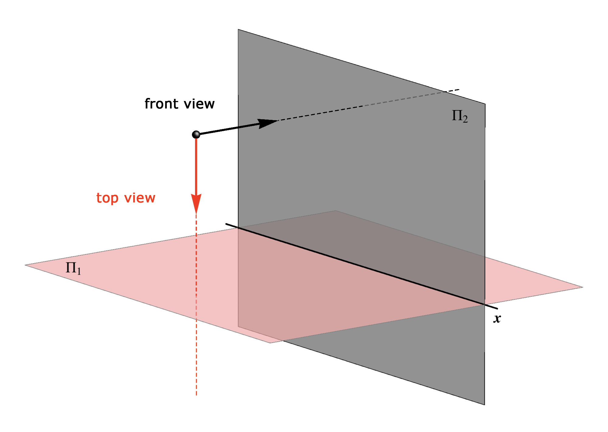
In the next examples it will be shown how to project solids with a base parallel to the projection plane and its visibility.In the orthogonal projection of a polyhedra only the projection of its edges and vertices are drawn.
Contour and edges which are visible in a projection are drawn with a full line, and the edges that are invisible are drawn with a dashed line.
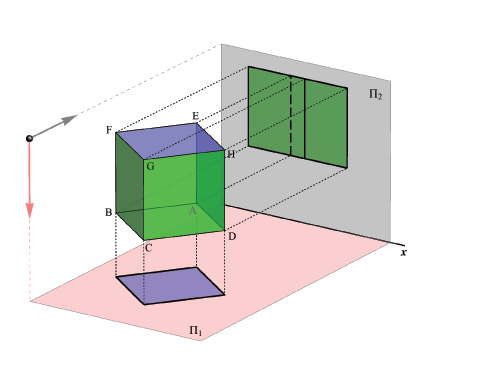
Example 1
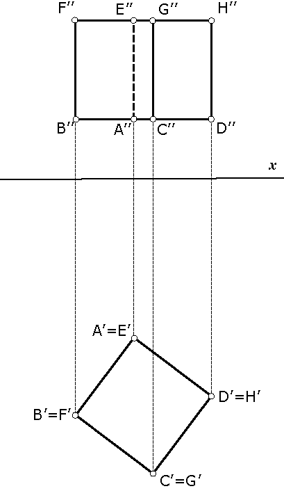
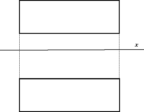
Let be given a cube with two faces parallel to the plane Π1.Horizontal projection of the cube is a square congruent with its face and only the face above will be visible. Therefore, the top view contour is the mentioned square.
The contour in the front view will be a rectangle and only the front two faces will be visible and the common edge along these faces. The other two faces are invisible and their common edge is drawn with a dashed line.
Which edges are projected in true size and in which projection?
 |
 |
Example 2
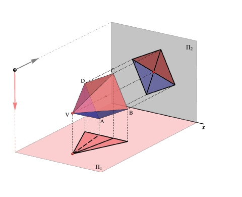
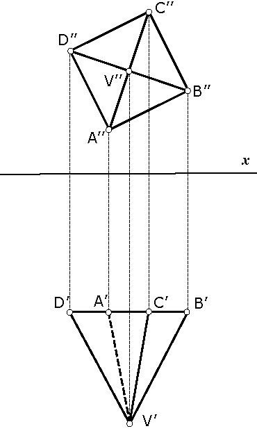
Let be given a regular 4-sided pyramid with a base parallel to the plane Π2.The top view contour is a triangle. Besides the contour edges, an upper edge of the lateral side is visible in the top view while the lower edge is covered, hence it is invisible.
The front view contour is a square coincident with the pyramid base. All edges of the lateral sides of the pyramid are visible in the front view because they are in front of the base.
On the picture the visible lateral sides of the pyramid are in pink color.
 |
 |
Example 3
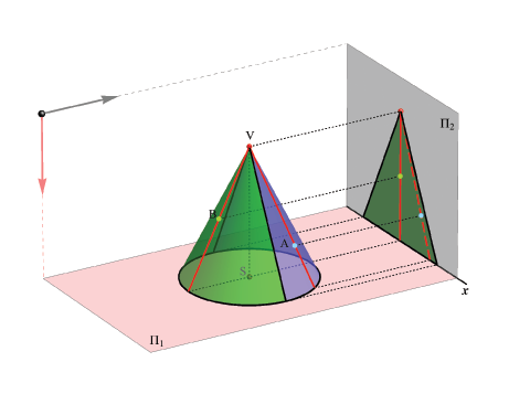
Let be given a cone with the base in the Π1 plane.Horizontal projection of the cone coincides with its base, hence it is a circle.
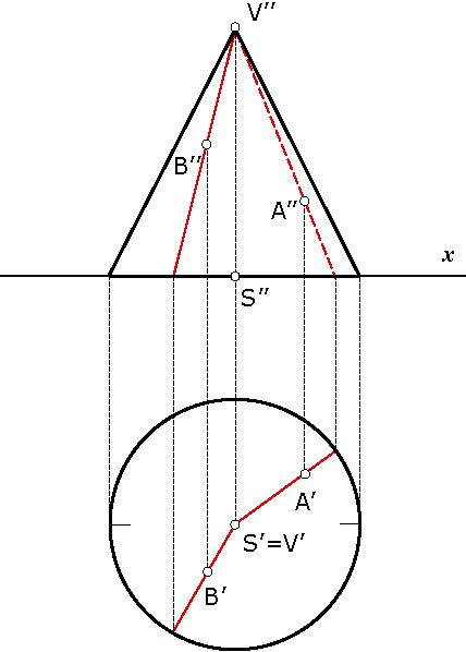
Vertical projection is a triangle where the contour lines are the generating lines (generatrices) of the cone which are parallel to the plane Π2.
The contour lines divide the lateral surface of the cone into two parts, one visible an another not visible in the front view.
If a point lies on a spatial object, but not on its edge, then the orthogonal projection of that point is determined by the projection of some line of the object surface that passes through the given point. The visibility of the point in the orthogonal projection depends on the visibility of the selected surface line. If the surface line is visible then the point is also visible, and vice versa.
In this example orthogonal projection of two points (A and B) lying on the cone surface are shown. The projections are determined by constructing the projections of the generatrices of the cone that pass through the points (lines connecting points A and B with the cone apex). The generatrix lying on the font side of the cone is visible in the front view (hence, also the point B is visible), while the generatrix passing through point A is on the back side of the cone and therefore is invisible in the front view (and also the point A is invisible).
 |
 |
Example 4
|

|
|
Created by Sonja Gorjanc 3DGeomTeh - Developing project of the University of Zagreb. |