Defining a plane by three numbers
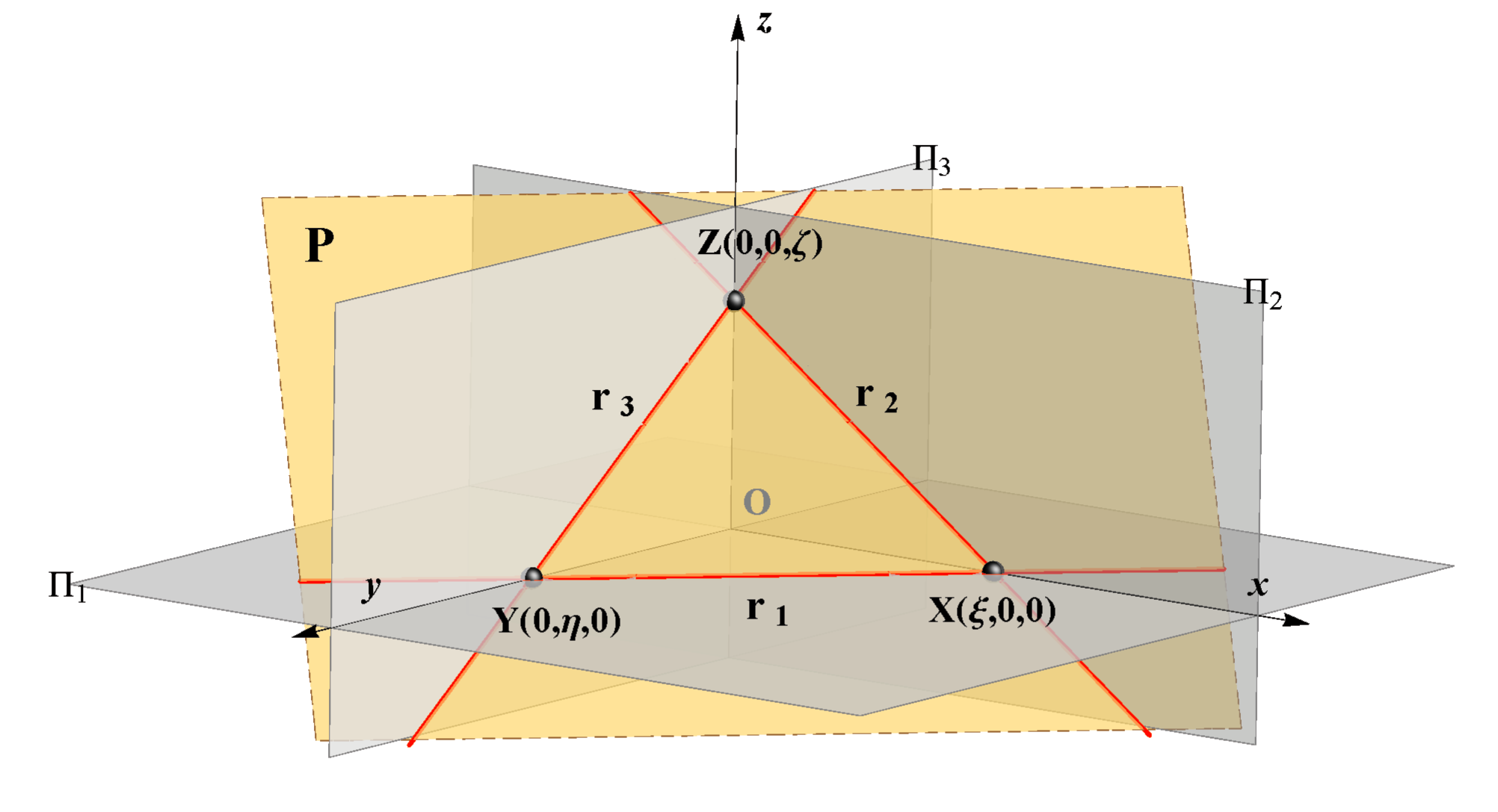
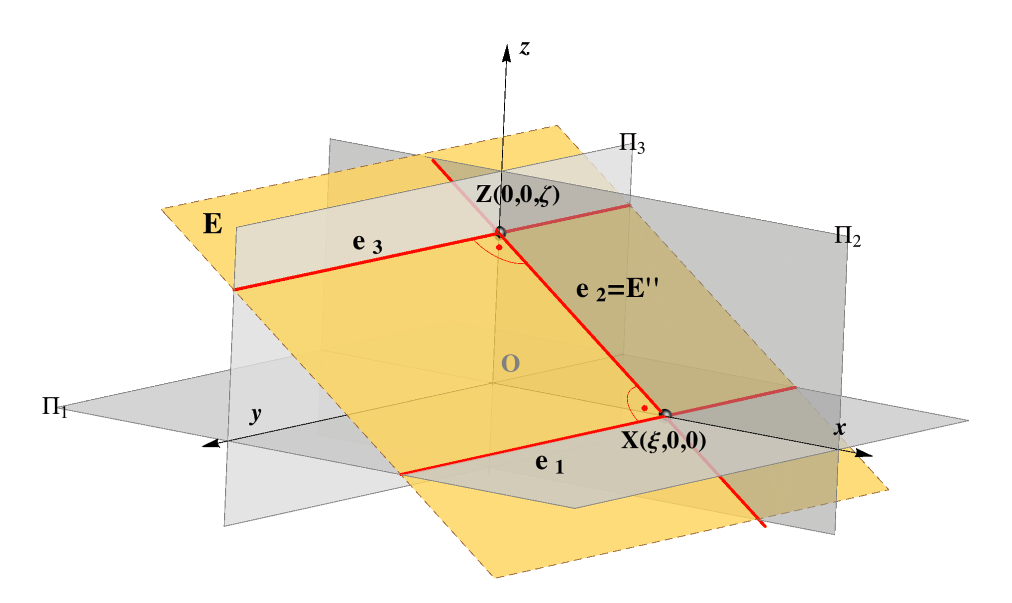
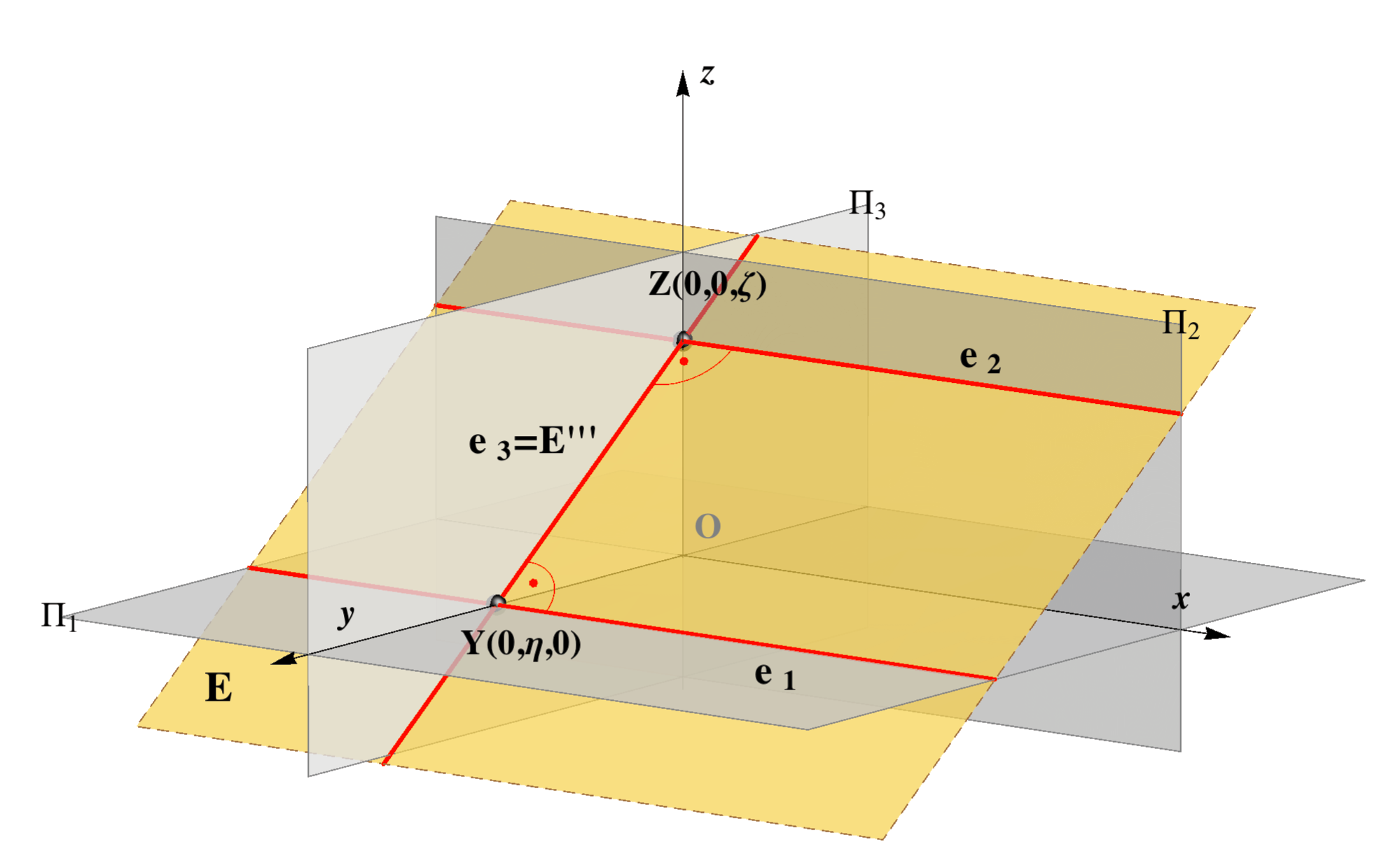
Any plane that does not contain the origin O(x,y,z) of the coordinate system, it is intersected by the coordinate axes in three points:X = x ∩ P, the intersection point of the axis x and the plane P,
Y = y ∩ P, the intersection point of the axis y and the plane P,
Z = z ∩ P, the intersection point of the axis z and the plane P.
Let us denote the three intersection points:
X = (ξ,0,0),
 Y = (0,η,0), Z = (ζ,0,0),
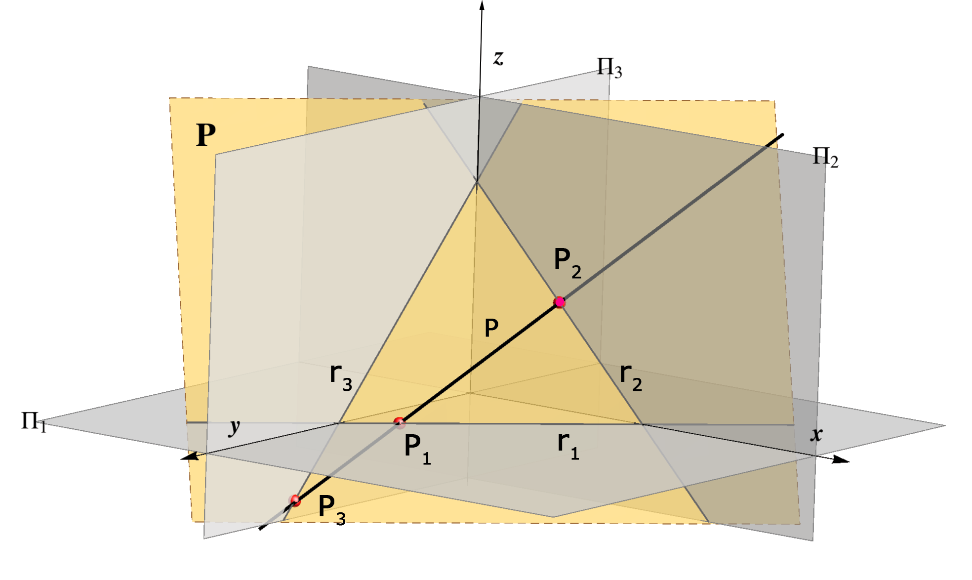
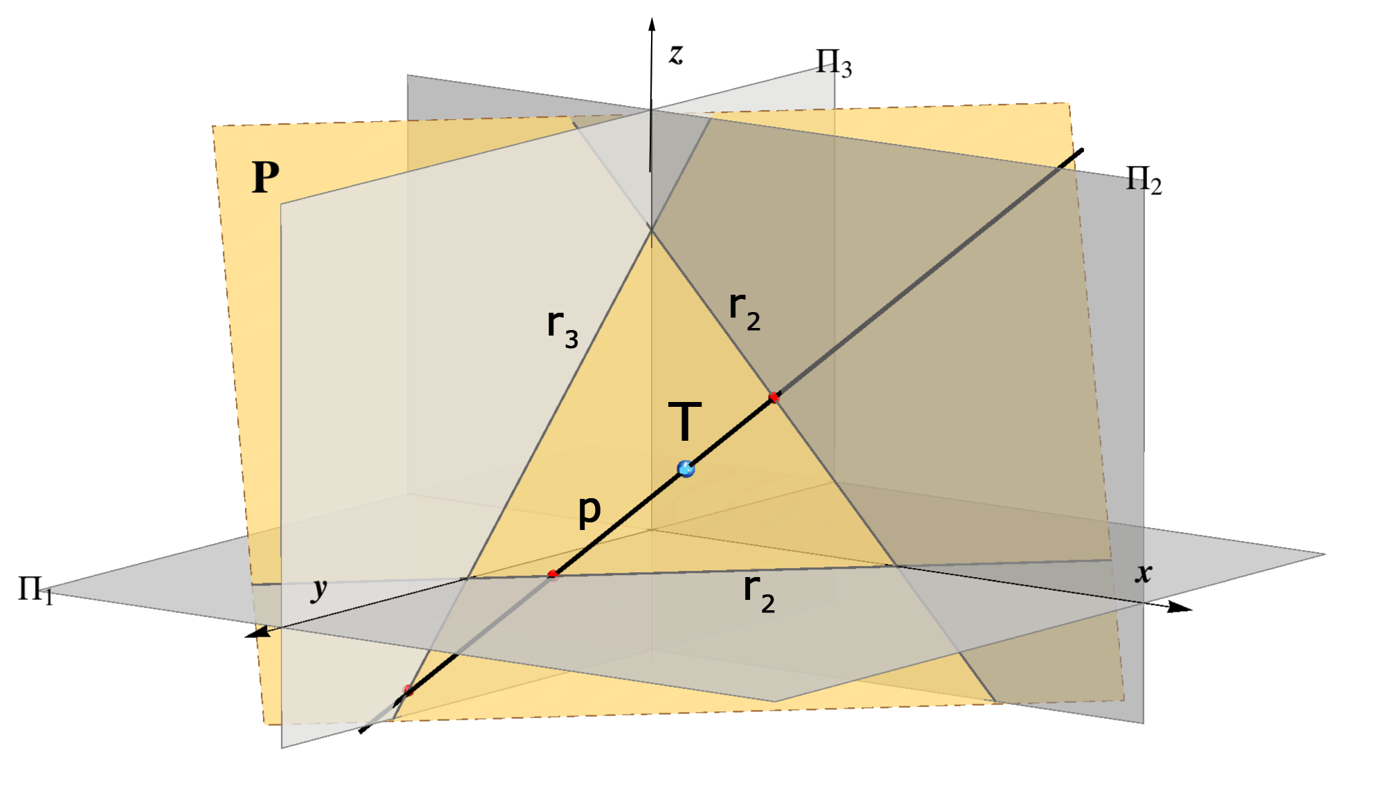
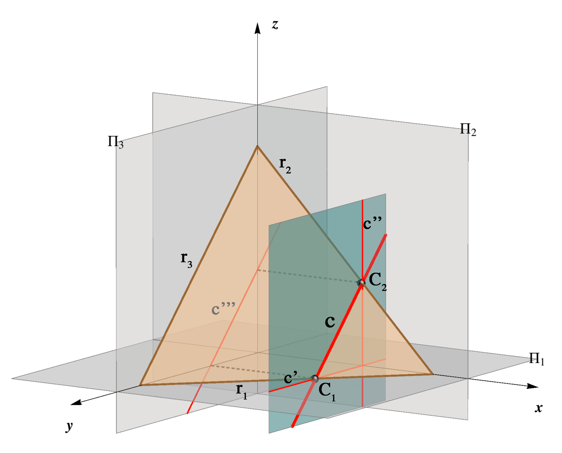
then it is clear that the three numbers (ξ,η,ζ) determine uniquely the position of a plane in the space as well as its traces. It is shown in the figure below.
 |
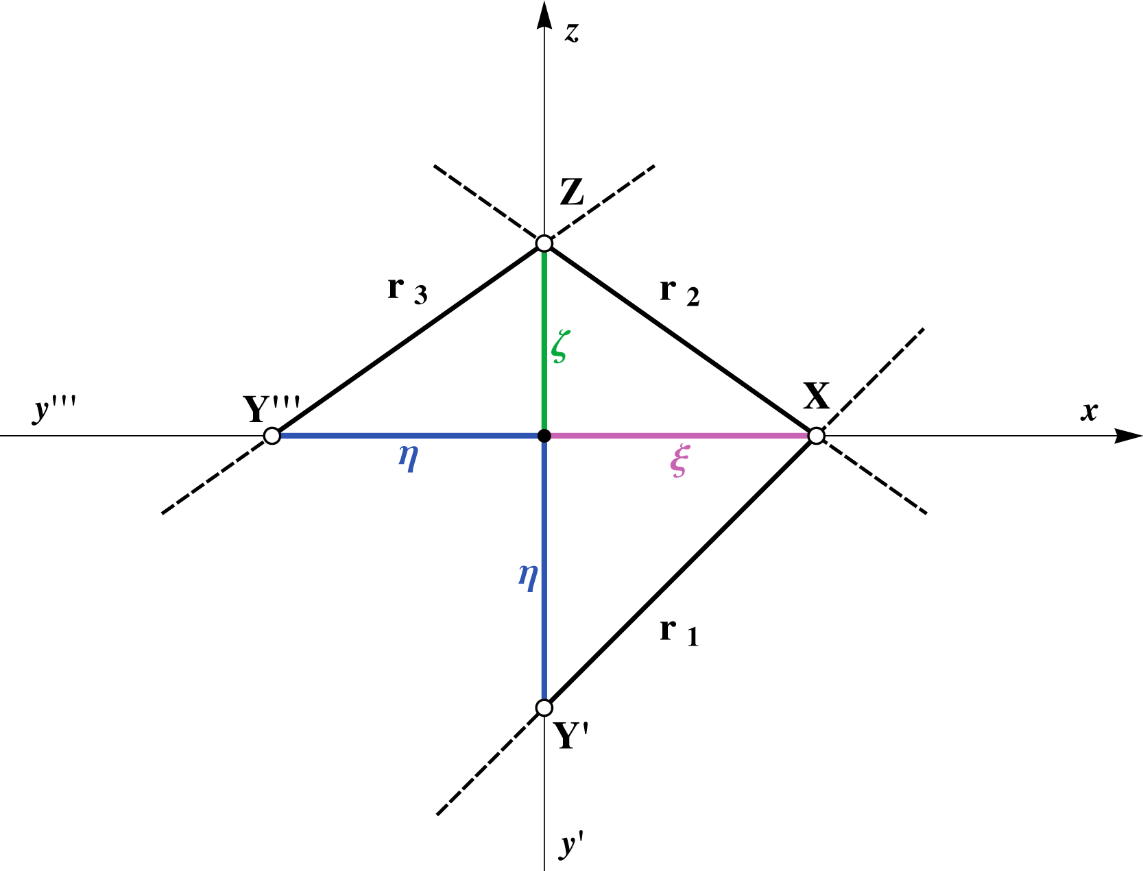 |
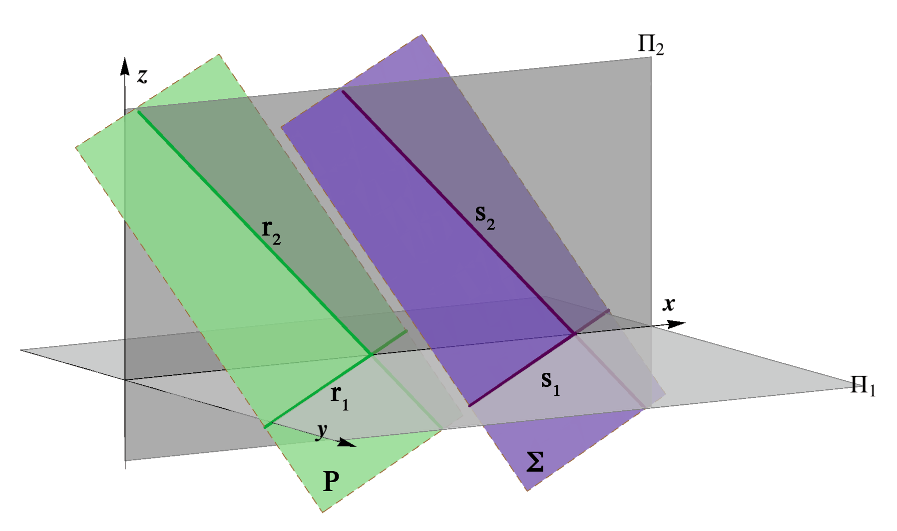
r1 ∩ r2 = X ∈ x,
r1 ∩ r3 = Y ∈ y,
r2 ∩ r3 = Z ∈ z.
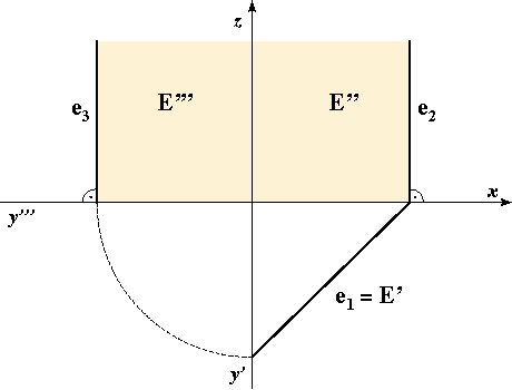
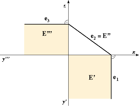
This means that the horizontal trace is drawn as a solid line beneath the x axis and on the right side of y' axis.
Assignment 1: Construct and label the traces of the following planes: A(4,2,3), B(3,2,–4), Γ(4,2,∞), Δ(4,∞,2) and E(∞,4,2).
We will mostly draw only the horizontal and vertical traces. If it is so, they will be drawn as a solid line in the following way: the horizontal trace is the solid line beneath the x axis, and the vertical trace is the solid line above the x axis.
Assignment 2: Construct and label the horizontal and vertical traces of the following planes:
Σ(–4,2,5), Κ(–4,–2,5), Ω(–4,–2,–5), Λ(–4,–2,∞), Φ(–4,∞,–5), Ψ(∞,–2,–5), Ζ(∞,∞,2), Τ(∞,2,∞) and Θ(2,∞,∞).
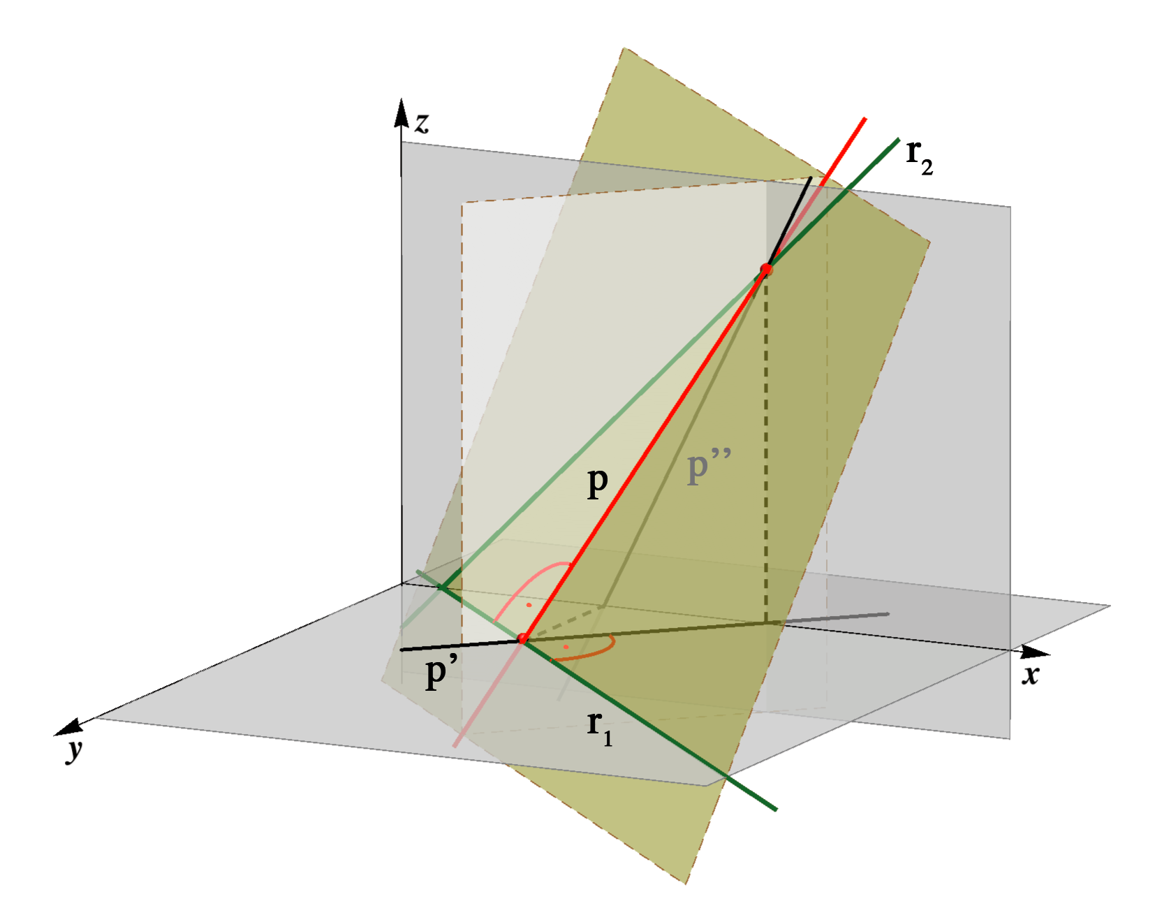
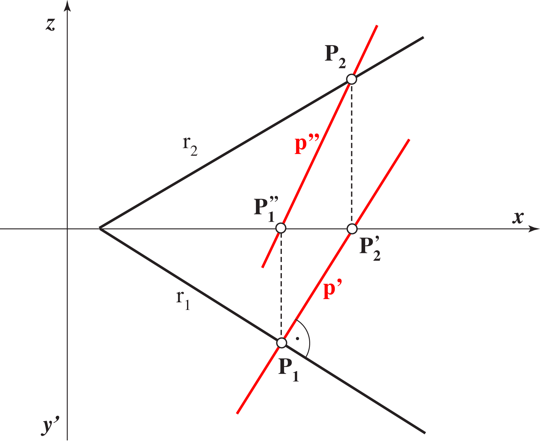
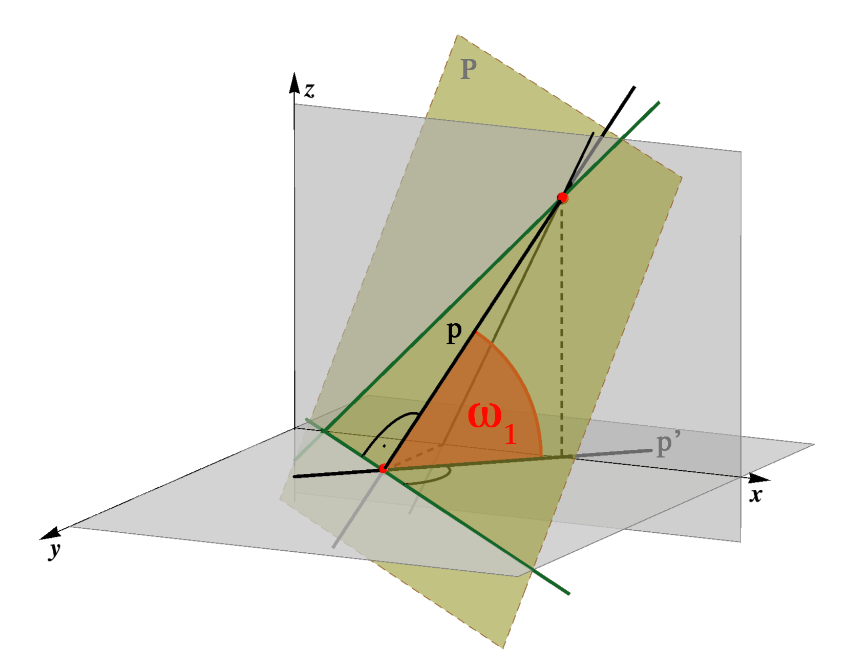
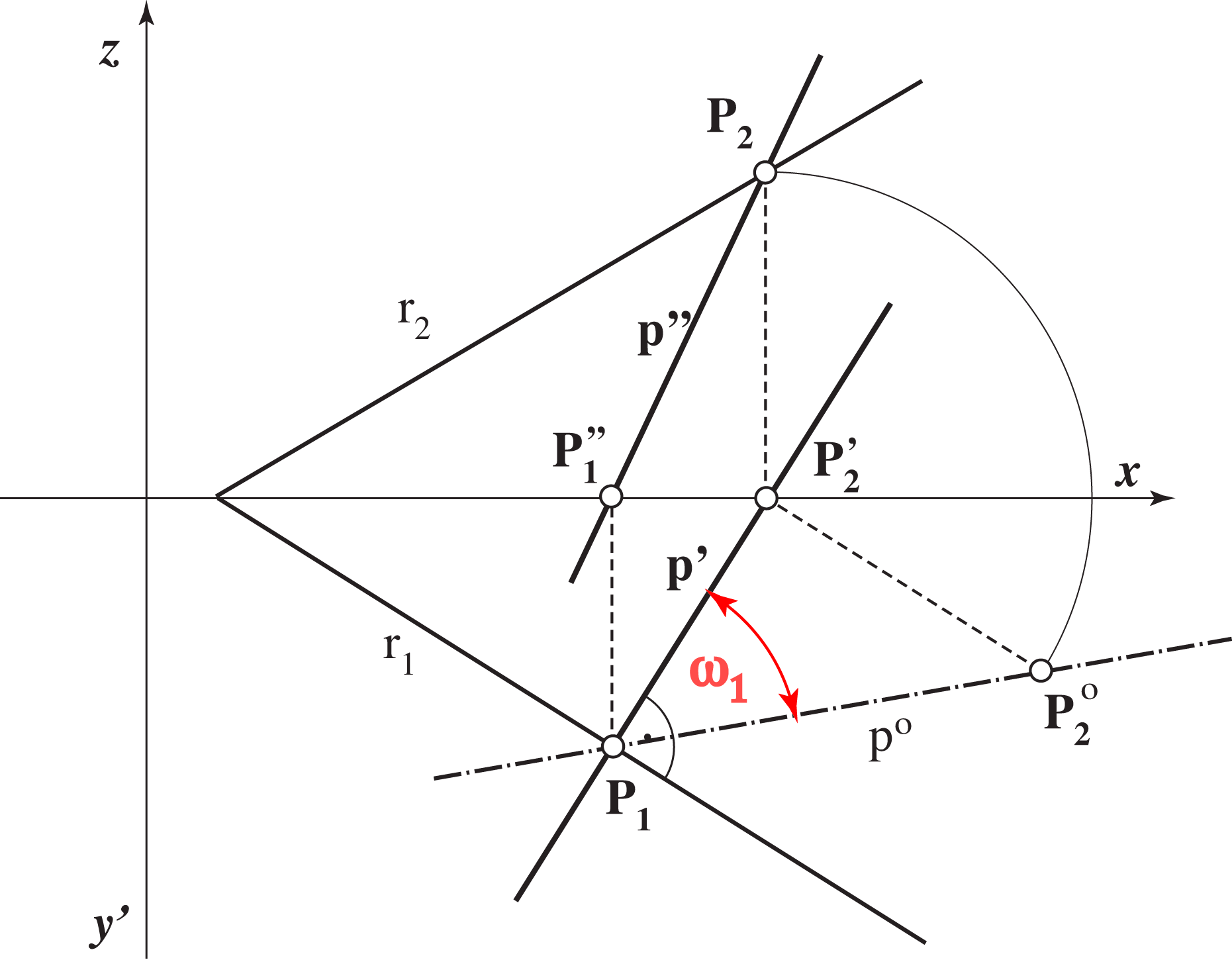
Visualization of the change of the traces
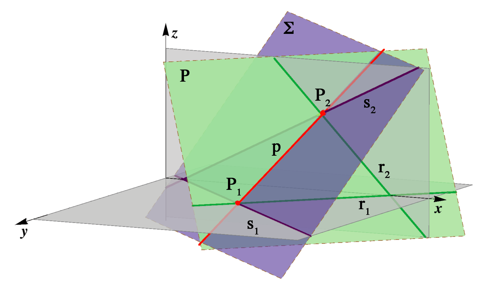
The following animation shows how the vertical and profile traces change during the rotation of the plane about its horizontal trace. Vertical and profile traces always intersect in a point lying on the z axis.
Animation starts by clicking in the figure above.
Planes in special positions
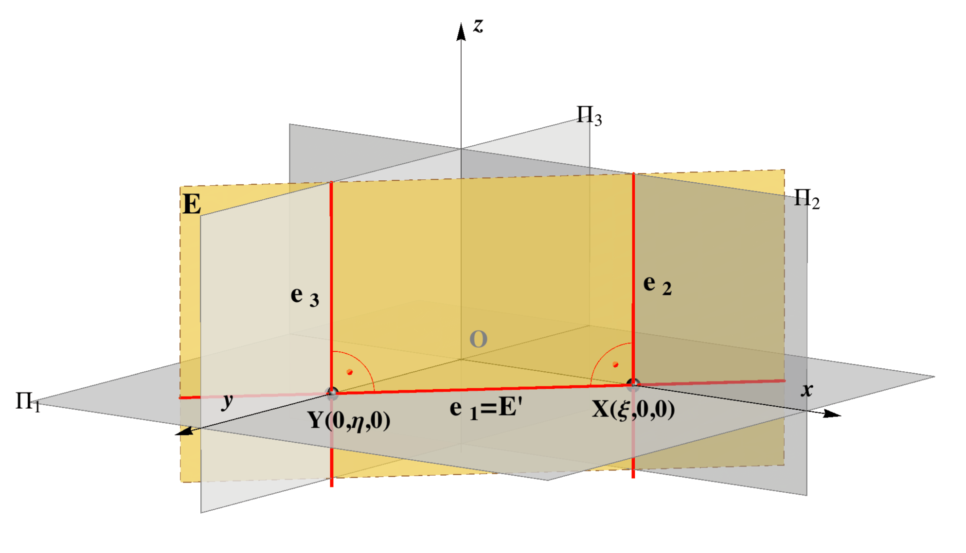
Projecting planes
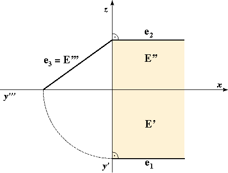
Planes perpendicular to at least one plane of projection are parallel to at least one coordinate axis. Therefore, their image in that projection is a line - corresponding trace.| horizontal projecting plane
E E ⊥ Π1, E || z e1 = E' |
vertical projecting plane
E E ⊥ Π2, E || y e2 = E'' |
profile projecting plane
E E ⊥ Π3, E || x e3 = E''' |
 |
 |
 |
 |
 |
 |
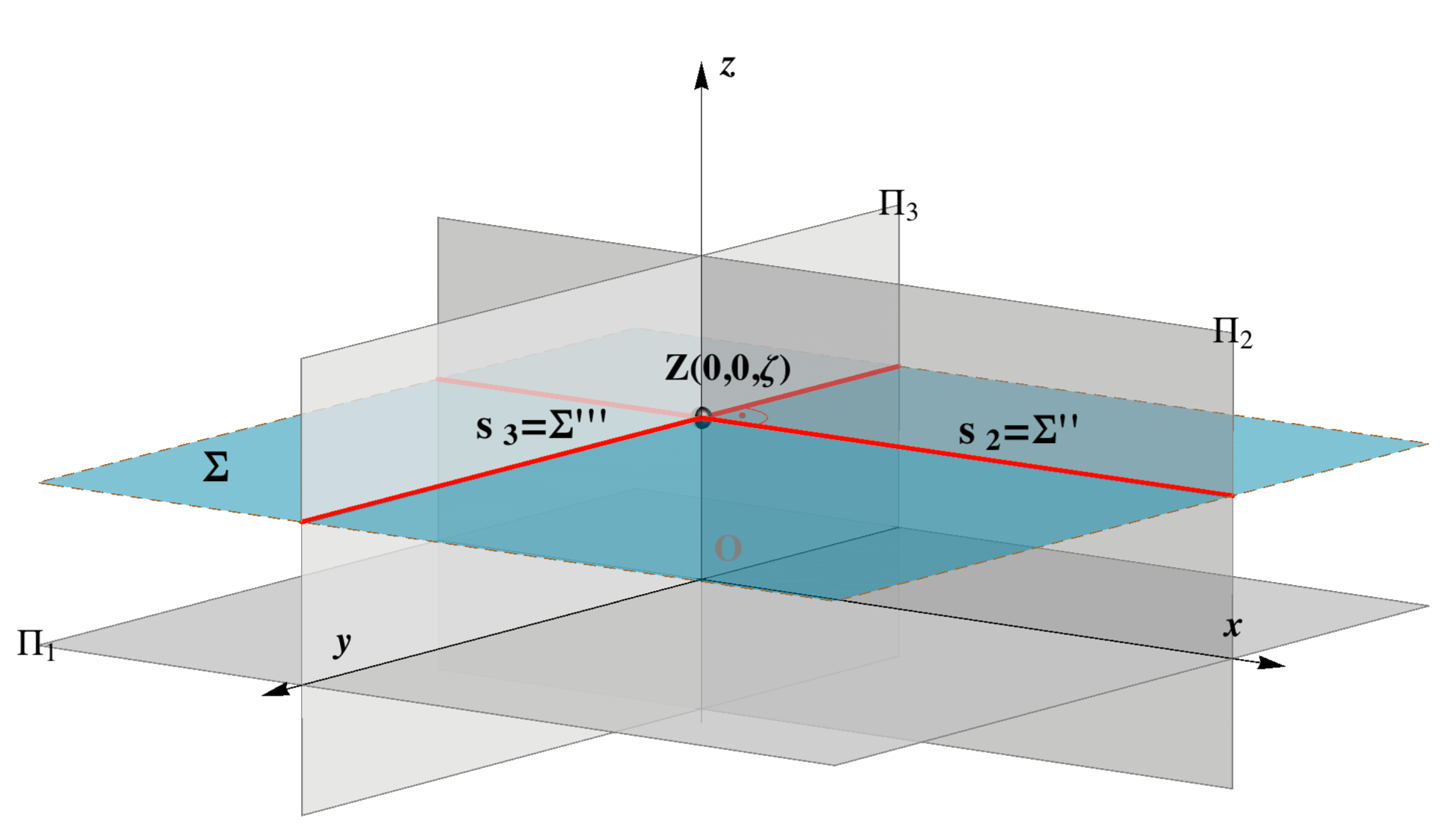
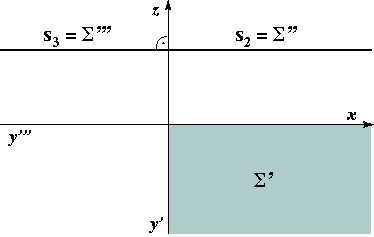
| Σ ||
Π1, Σ ⊥ z
Σ ⊥ Π2, Π3 Σ || x, y |
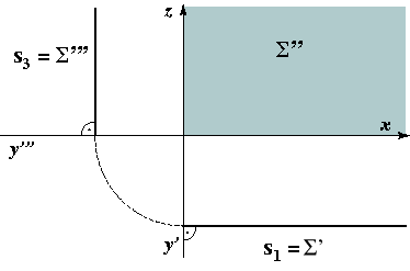
Σ ||
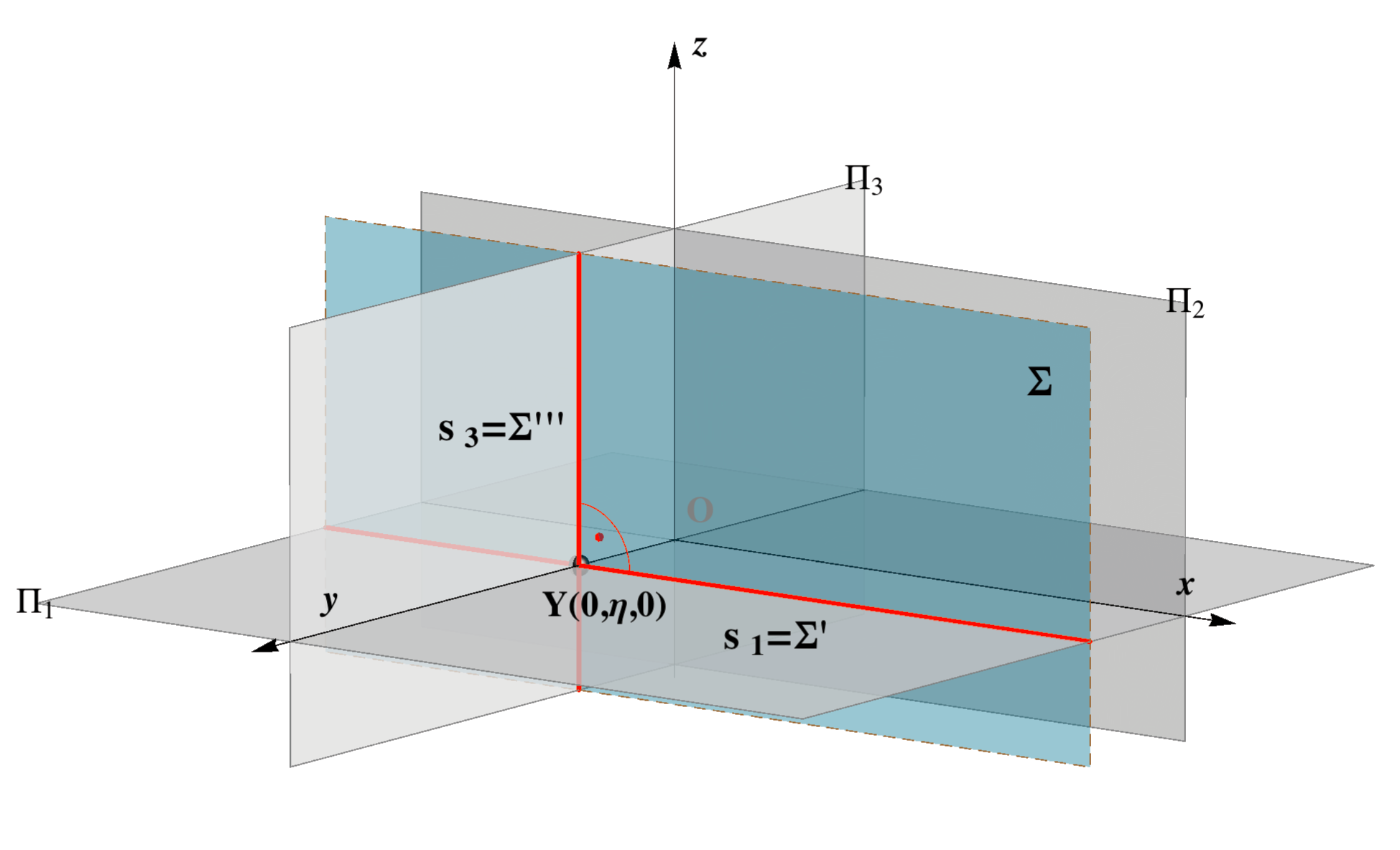
Π2, Σ ⊥ y
Σ ⊥ Π1, Π3 Σ || x, z |
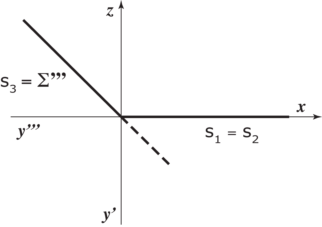
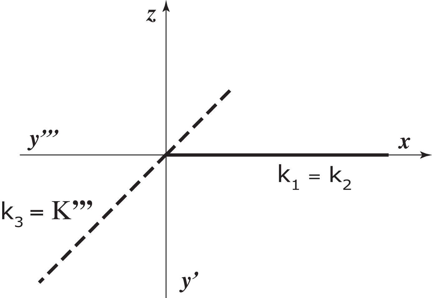
Σ ||
Π3, Σ ⊥ x
Σ ⊥ Π1, Π2 Σ || y, z |
 |
 |
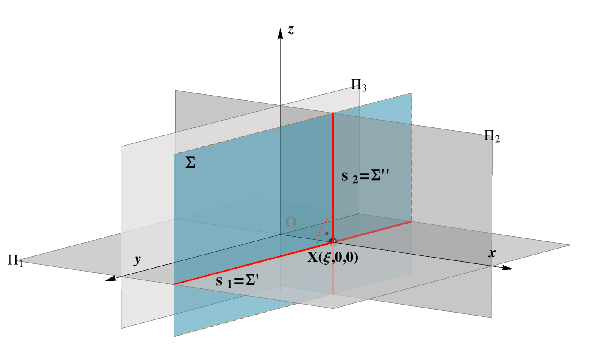 |
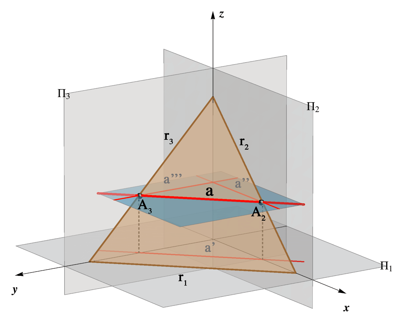
| Trace s1 is the line
at infinity of the plane Π1. This type of planes are called horizontal planes. |
Trace s2 is the line
at infinity of the plane Π2. This type of planes are called vertical planes. |
Trace s3 is the line
at infinity of the plane Π3. This type of planes are called profile planes. |
 |
 |
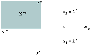 |
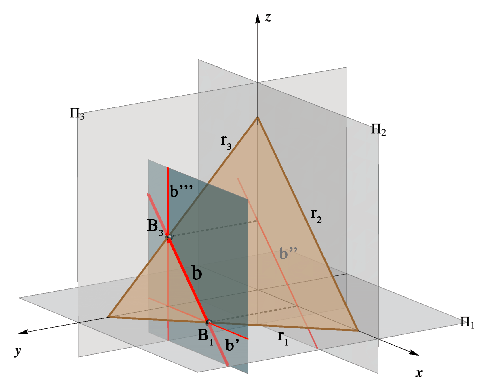
On these image we highlight the areas where the points of the plane that lie in the 1. octant are projected.
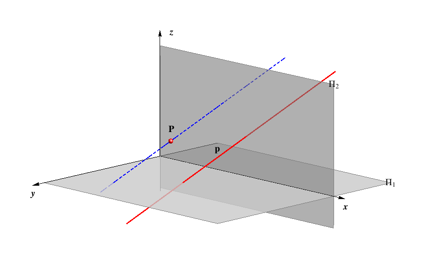
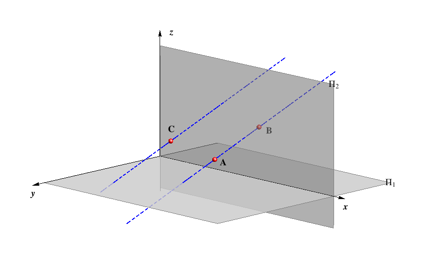
Planes that contain the origin O
Traces of these planes are not uniquely determined by the triplet of numbers (ξ,η,ζ) .For instance, Ρ(0,0,0) indicates only that Ρ contains the origin, Ρ(∞,0,0), Ρ(0,∞,0) or Ρ(0,0,∞) indicate that the plane contain the axis x, y or z.
In this situation, we require more data on the plane.