PRIMJER ( zid )
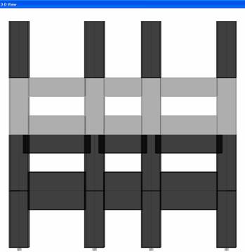
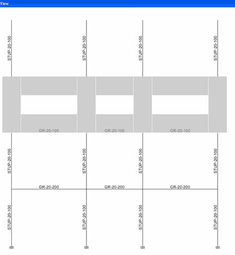
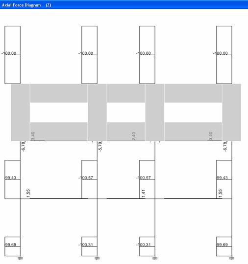
Horizontalno opterećenje
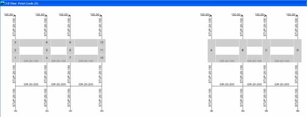
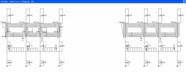
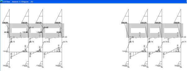
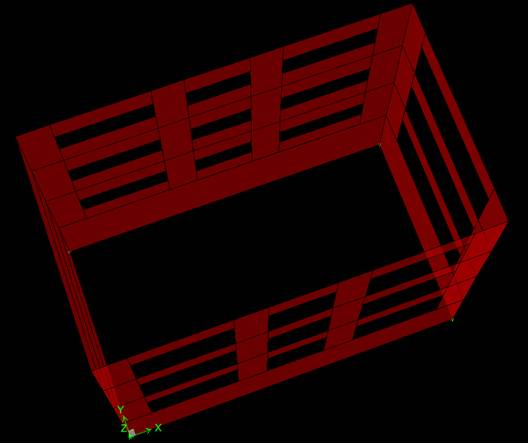
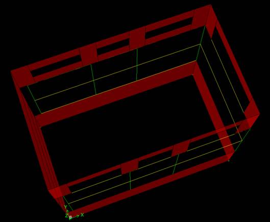
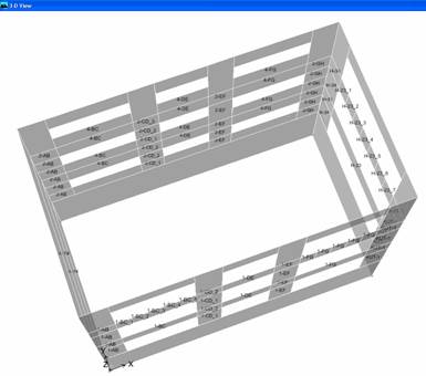
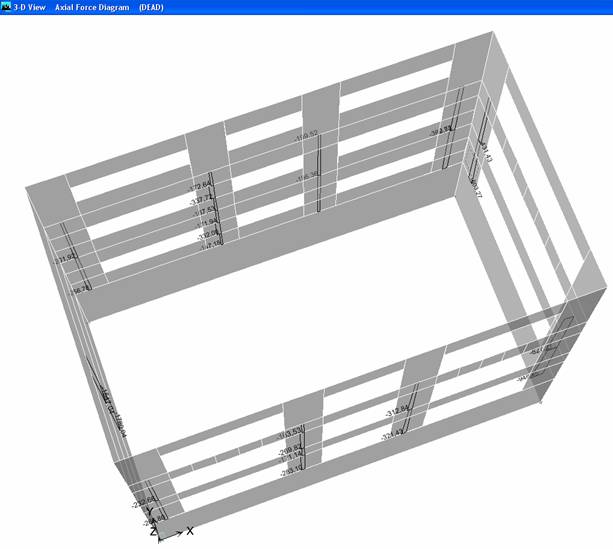

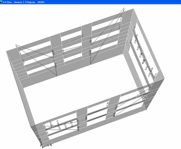
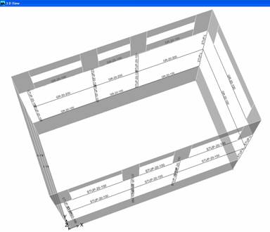
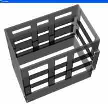
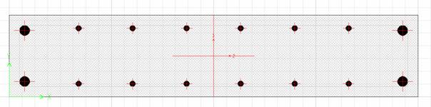
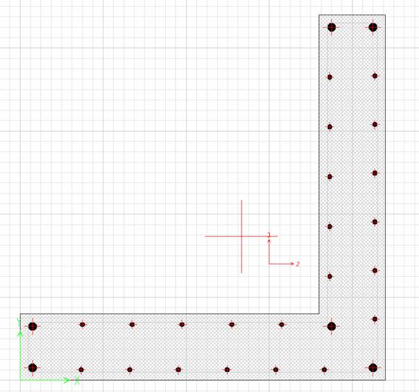
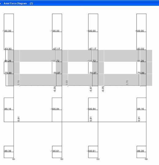
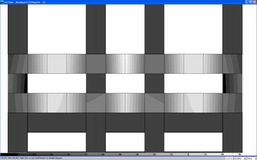
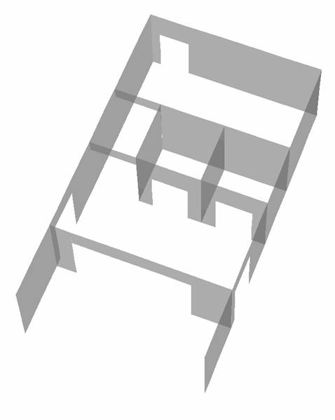
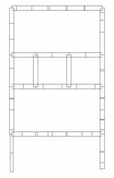
ZIDOVI JEZGRE
(poslovna zgrada Heinzelova)
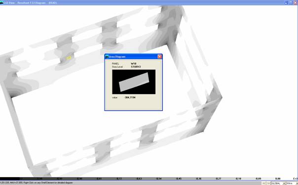
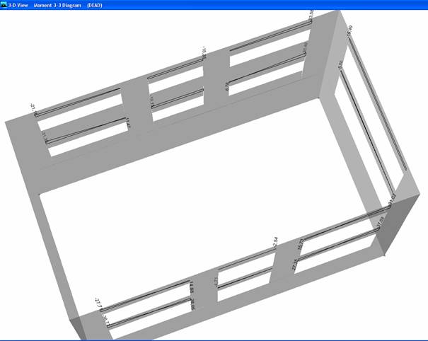
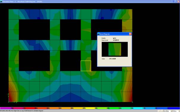
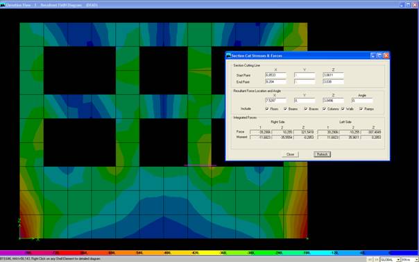
karakteristična mjesta:
![]()
![]()
![]()
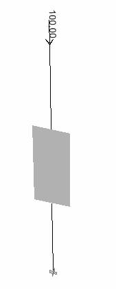
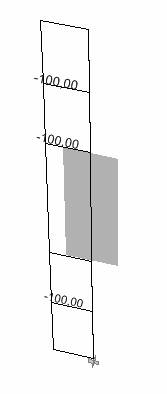
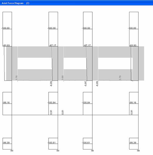
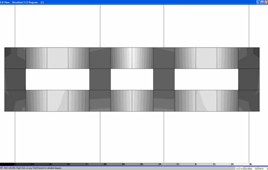
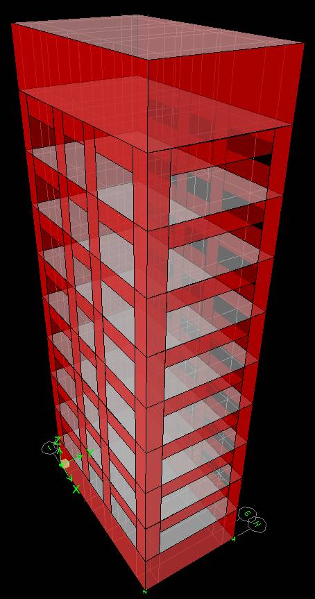
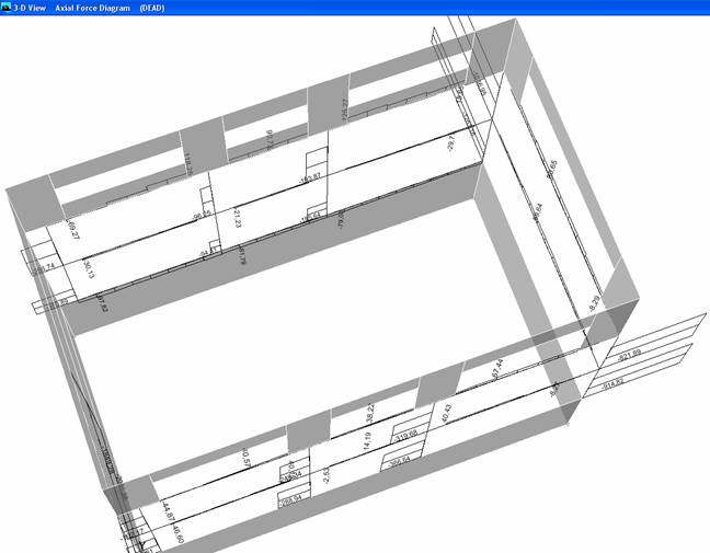
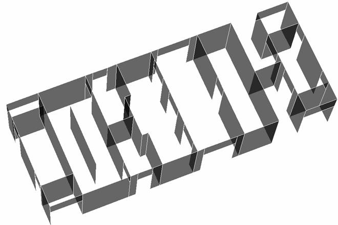
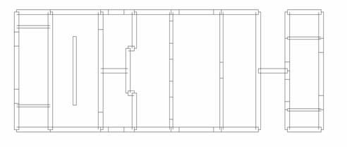
ZIDOVI JEZGRE
(poslovna zgrada ZG TOWER - toranj)
karakteristična mjesta:
![]()
![]()
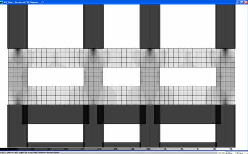
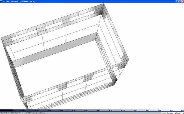
Output Convention for Shell Element Internal Forces
The shell element internal forces, like stresses, act throughout the element. They are present at every point on the midsurface of the shell element. ETABS reports values for the shell internal forces at the element nodes. It is important to note that the internal forces are reported as forces and moments per unit of in-plane length.
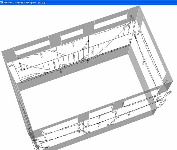
The basic shell element forces and moments are identified as F11, F22, F12, M11, M22, M12, V13 and V23. You might expect that there would also be an F21 and M21, but F21 is always equal to F12 and M21 is always equal to M12, so it is not actually necessary to report F21 and M21.
The figure below shows internal F11 forces acting on the midsurface of a shell element. In the figure, the force distribution labeled (a) represents an actual F11 force distribution. The force distribution labeled (b) shows how ETABS calculates only the internal forces at the corner points of the shell element. Note that we could calculate these stresses at any location on the shell element. We simply choose to calculate them only at the corner points because that is a convenient location and it keeps the amount of output to a reasonable volume.
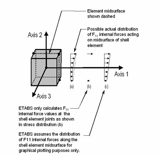
The force distribution labeled (c) in the figure above shows how ETABS assumes that the F11 forces vary linearly along the length of the shell element between the calculated F11 force values at the element nodes for graphical plotting purposes only.
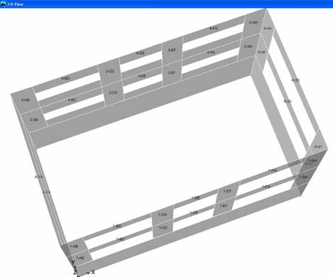
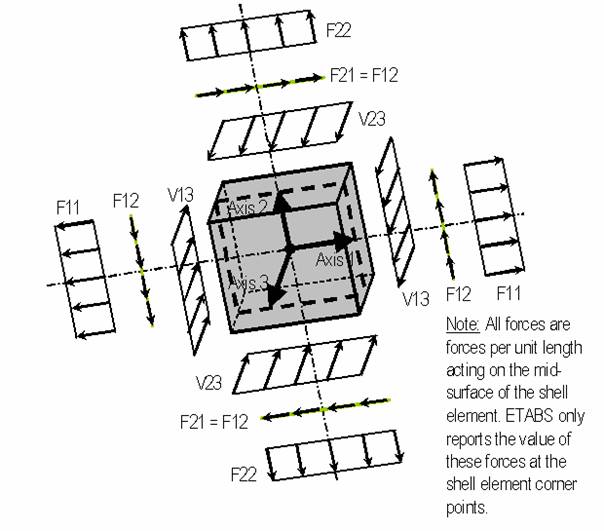
The figure below illustrates the positive directions for shell element internal forces F11, F22, F12, V13 and V23. Note that these shell element internal forces are forces per unit length acting on the midsurface of the shell element. ETABS only reports the value of these forces at the shell element corner points.
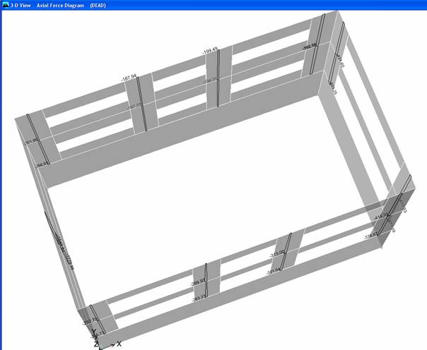
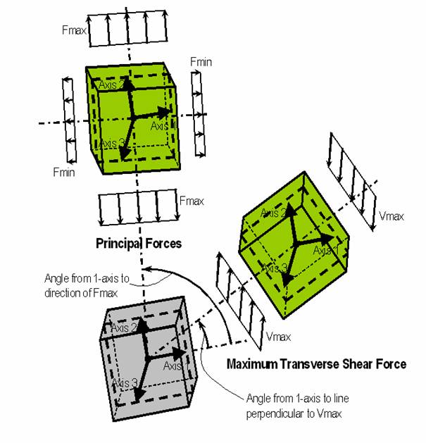
The figure below illustrates the positive direction for shell element principal forces, Fmax and Fmin. It also illustrates the positive direction for the shell element maximum transverse shear force, Vmax.
Dimenzioniranje / Provjera nosivosti zida